The hydraulic system of a John Deere tractor plays a crucial role in powering various essential functions, from lifting implements to steering. In this article, we will delve into how the hydraulic system works, how to maintain it, and what to do when troubleshooting becomes necessary.
I will discuss the John Deere Hydraulic System Diagram, it’s major parts and most common system failures which you can fix by following the proper expert guidance. So let’s start with talking about what is a Hydraulic system and how it works.
A hydraulic system is like a team effort of liquids and parts. When you push on a special liquid, it moves around and helps things work. This power helps tractors lift heavy things and move equipment smoothly. It’s like a secret helper for big machines. When you need things to go up, down, or move, the hydraulic system is there to make it happen! We also have a well explain content on John Deere Hy Gard™ Alternative Oil.
John Deere Hydraulic System Diagram & Parts
The John Deere Hydraulic System Diagram is important because it’s like a map that guides us in understanding how the hydraulic system works in tractors. It helps us fix problems, maintain the system, and use it efficiently. It’s a tool that makes sure everything runs smoothly on the farm! You probably also need to read Rural King Tractors Are Junk?.
The hydraulic system of a John Deere tractor operates seamlessly due to the interplay of 24 crucial components. Each part plays a unique role, contributing to the system’s efficiency and functionality. Let’s delve into these components to better comprehend their significance.
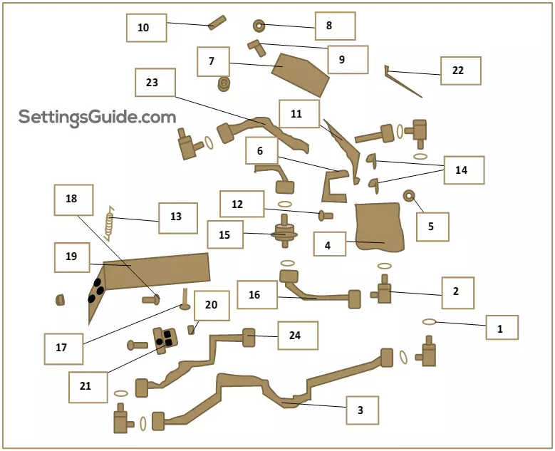
1. O Ring
The O-ring, resembling a simple rubber band, might seem unassuming, but it plays a crucial role. Positioned over the elbow fitting, it serves as a barrier, effectively preventing the intrusion of liquids or gases into unwanted areas. This not only ensures the integrity of the hydraulic system but also helps maintain the desired pressure levels.
2. Elbow Fitting
The elbow fitting isn’t just another piece in the puzzle; it provides flexibility and adaptability to the system. By allowing the oil tube and hydraulic line to change directions smoothly, it ensures that the hydraulic system can be efficiently routed, even when space is limited. This component is a testament to smart engineering that simplifies intricate designs.
3. Oil Tube
Despite its small size, the oil tube has a significant role to play. This slender conduit serves as the channel through which oil is conveyed to specific destinations. Connecting to the lock nut via the elbow fitting and O-ring, the oil tube is the circulatory system of the hydraulic mechanism, ensuring that the fluid reaches where it’s needed most.
4. Pressure Relief Valve (PRV)
The PRV, often referred to as a relief valve, is like a guardian of the hydraulic system. Its primary function is to limit the pressure within the system, preventing it from exceeding safe levels. By doing so, it not only protects the components from damage but also ensures that the fluid flows through the system at a controlled rate, contributing to its efficient operation.
5. Lock Nut
The lock nut might appear as a simple threaded fastener, but its purpose is anything but ordinary. This unassuming component serves as the safeguard against vibrations and potential movements that might disrupt the hydraulic system’s stability. By resisting the forces that would otherwise cause a loose connection, the lock nut plays a vital role in maintaining the system’s reliability.
6. Hook
The hook is a modest yet ingenious piece that facilitates the linkage between components. Resembling a U-shaped tool, the hook works in tandem with strong locking pins to secure the lever into the pressure relief valve. This seemingly small feature ensures that the lever can function smoothly and effectively, translating operator input into controlled hydraulic actions.
7. Quadrant
The quadrant might appear as a holder, but it’s much more than that. It provides the stable base upon which the lever, knob, push nut, and insert are positioned. The intricate interplay of these components within the quadrant ensures that the lever’s movement is controlled and accurate, enabling precise adjustments to the hydraulic system’s behavior.
8. Push Nut
The push nut is a testament to simplicity and efficiency. As a cost-effective fastener, it requires a simple push to secure another component. This seemingly basic feature is highly versatile, making it an ideal choice for securing shafts and tubes in the hydraulic system.
9. Knob
The knob might seem like a minor detail, but it serves a critical purpose in ensuring operator comfort and control. By keeping the lever upright, the knob provides a convenient point of interaction for the operator, allowing them to grasp and manipulate the lever with ease. This ergonomic consideration enhances the overall user experience.
10. Insert
The insert, often overlooked, is a component that reinforces stability and strength. Situated atop the push nut and knob, its brushed finish and strategic placement ensure that the knob remains securely in position. While its function might seem subtle, it contributes significantly to the system’s overall robustness.
11. Lever
The lever is a central component that empowers the operator to dictate the system’s behavior. By engaging with the relief valve through the single hook mechanism, the lever allows for the adjustment of gears, enabling transitions between high and low settings. This dynamic feature puts control directly into the hands of the operator.
12. Pin Fastener
The pin fastener, often referred to as a steel pin, plays a role that goes beyond its simple appearance. By maintaining alignment and secure joints between components, it ensures that the system operates as a cohesive unit. This seemingly minor component is essential for preventing misalignment and preserving the integrity of the hydraulic system.
13. Extension Spring
The extension spring is an unsung hero within the hydraulic system. This component stores and releases energy, effectively acting as a bridge between two gears. As these gears attempt to separate, the extension spring’s elastic force prevents their disengagement, promoting smooth and controlled transitions between different operational states.
14. Spring Locking Pin
The spring locking pin is a small yet critical part that plays a significant role in the system’s operation. Functioning as a secure connection point, it holds the hook in place, allowing for the effective engagement of the lever with locking mechanisms. This straightforward yet effective solution ensures that the lever can be operated with confidence and accuracy.
15. Hydraulic Filter
The hydraulic filter is an unsung hero when it comes to the system’s health and longevity. By meticulously removing dirt and particles from the hydraulic fluid, it maintains the fluid’s cleanliness. This not only prolongs the life of the hydraulic system but also ensures the efficient and uninterrupted flow of fluid, critical for the system’s overall performance.
16. Tube
While often overlooked, the tube is a vital conduit within the hydraulic system. It provides the pathways through which hydraulic fluid, gases, and oils travel, facilitating the system’s operation. Typically crafted from robust materials like metal, these tubes enable the seamless flow of fluids, ensuring that the hydraulic system’s various components work in harmony.
17. Bolt
The bolt might be a seemingly basic component, but it plays an essential role in securing various elements within the hydraulic system. With its head and cylindrical body, the bolt is threaded into place, providing a sturdy anchor for other components. Paired with a flange nut, it forms a reliable connection, contributing to the system’s overall stability.
18. Screw
The screw, with its extensive threads and sealing properties, is a key player in the hydraulic system’s structure. By engaging within the bracket’s hole, the screw ensures a secure attachment, preventing unwanted movement and guaranteeing a strong seal. Available in various materials, the screw’s role in the hydraulic system is indispensable.
19. Bracket
The bracket serves as a fundamental support structure within the hydraulic system. Comprising a solid material like metal and featuring an array of small holes, the bracket provides the necessary framework for securing components like bolts, screws, and nuts. Its design is crucial for maintaining the system’s integrity and stability.
20. Flange Nut
The flange nut, while similar to a standard nut, boasts a unique design that offers increased stability. With a broader flange, it serves as a washer that resists twisting. When paired with a bolt, the flange nut ensures a secure and non-twistable connection, contributing to the hydraulic system’s reliability.
21. Clamp
The clamp might be a small and seemingly mundane component, but it has a critical role in the hydraulic system’s functionality. By compressing bolts and brackets with the help of a flange nut, the clamp creates a secure seal that prevents unintended movement or detachment. This unassuming component contributes to the system’s overall stability.
22. Tie Band
As an Original Equipment Manufacturer (OEM) part, the tie band serves a pivotal role in holding components together. Typically made from heavy-duty plastic or metal, tie bands secure elements within the hydraulic system, ensuring that they remain in place even under various stresses and vibrations.
23. Hydraulic Hose
The hydraulic hose is a flexible conduit that serves as a lifeline for the hydraulic system. Capable of transferring hydraulic fluid between different auxiliary and heavy-duty components, the hydraulic hose’s flexibility and armored design allow it to withstand high-pressure conditions. Its role in the system’s overall functionality cannot be overstated.
24. Hydraulic Line
Similar to the hydraulic hose but designed to withstand even greater heat, the hydraulic line is tasked with transporting fluid in specified directions. This component’s durability is critical, as it ensures the seamless transfer of hydraulic fluid under various conditions, contributing to the hydraulic system’s reliability.
How Does a Tractor Hydraulic System Work?
While talking about John Deere Hydraulic System Diagram, we need to know that a tractor’s hydraulic system operates on the principle of fluid mechanics and pressure. It consists of a hydraulic pump, which is usually powered by the engine, and hydraulic cylinders that utilize the pressurized hydraulic fluid to perform work. When the pump operates, it pushes hydraulic fluid into the cylinders, creating pressure that drives various components, such as the lift arms or steering mechanism.
A tractor’s hydraulic system operates on the principle of fluid mechanics and pressure, allowing it to perform various tasks efficiently. Here are some key aspects that illustrate how this system works:
Hydraulic Pump Power:
The system starts with a hydraulic pump, which is usually driven by the tractor’s engine. As the engine runs, it powers the pump, creating pressure in the hydraulic fluid.
Pressurized Fluid Transmission:
The pump pressurizes the hydraulic fluid, turning it into a powerful force that can be used to move various components. This pressurized fluid is then sent through hoses and pipes to reach the parts that need to be operated, such as cylinders or motors.
Hydraulic Cylinders and Motors:
Hydraulic cylinders and motors are responsible for converting the pressurized hydraulic fluid into mechanical movement. When the pressurized fluid enters a cylinder, it pushes against a piston, creating a force that moves the piston and, consequently, the attached machinery. Similarly, hydraulic motors use the fluid’s pressure to generate rotational movement.
Valves for Control:
Valves play a crucial role in controlling the flow of hydraulic fluid. Directional control valves determine the path of the fluid, guiding it to the desired component. Flow control valves regulate the speed at which the fluid moves, allowing for precise control over the system’s actions.
Return and Reservoir:
After the hydraulic fluid has performed its work, it needs a way to return to the reservoir. This is usually done through a separate set of hoses or pipes. The reservoir holds the hydraulic fluid, providing a steady supply for the system to function properly.
Where Do You Put Hydraulic Fluid on a John Deere Tractor?
To keep the hydraulic system running smoothly, it’s important to maintain the right fluid level. Most John Deere tractors have a hydraulic fluid reservoir located near the engine. Simply remove the cap, and add the recommended hydraulic fluid until it reaches the appropriate level, as indicated in the operator’s manual. Go ahead and also read Kawasaki vs Briggs and Stratton.
Maintaining the proper hydraulic fluid level in your John Deere tractor is essential for its optimal performance. Here’s a breakdown of how and where to add hydraulic fluid:
Locating the Reservoir:
The hydraulic fluid reservoir is typically situated near the tractor’s engine. It’s important to consult your tractor’s manual to pinpoint the exact location, as it may vary depending on the model.
Accessing the Reservoir:
Open the tractor’s hood or access panels to reach the hydraulic fluid reservoir. Some models might have a designated cap or lid for the reservoir, making it easy to identify.
Checking the Fluid Level:
Before adding hydraulic fluid, check the current level. There is usually a dipstick or level indicator attached to the reservoir. Ensure the fluid level is within the recommended range.
Using the Right Fluid:
It’s crucial to use the hydraulic fluid recommended by John Deere for your specific tractor model. Using the correct fluid ensures compatibility and optimal performance.
Adding Fluid:
Carefully remove the reservoir cap or lid, and add the hydraulic fluid using a funnel if necessary. Add fluid gradually to prevent overfilling.
Checking After Adding:
After adding hydraulic fluid, double-check the fluid level using the dipstick or level indicator. Make sure the level is within the specified range.
What Causes a Tractor Hydraulic System to Fail?
Several factors can contribute to hydraulic system failure. Common culprits include contamination of the hydraulic fluid, worn-out seals, or a malfunctioning pump. Additionally, overheating due to heavy usage without proper cooling can lead to reduced efficiency and even system breakdown.
Understanding John Deere Hydraulic System Diagram and the factors that can lead to hydraulic system failure in your tractor is crucial for timely maintenance and prevention. Here are some key reasons why a tractor’s hydraulic system might experience issues:
Contaminated Hydraulic Fluid:
Contaminants like dirt, debris, and water can find their way into the hydraulic fluid, causing clogs and reduced efficiency. This can lead to poor performance and potential damage to system components.
Worn Seals and O-Rings:
Seals and O-rings in the hydraulic system prevent fluid leakage. Over time, these seals can become worn or damaged, causing fluid to leak out and reducing the system’s pressure and effectiveness.
Malfunctioning Pump:
The hydraulic pump is the heart of the system, creating the necessary pressure for fluid movement. If the pump becomes worn, damaged, or fails, the entire system’s performance can suffer.
Overheating:
Excessive heat can degrade the quality of hydraulic fluid and lead to system inefficiencies. Overheating can be caused by prolonged, heavy usage without proper cooling.
Air in the System:
Air bubbles in the hydraulic fluid can disrupt the system’s efficiency. Air can be introduced during maintenance or due to leaks, causing erratic performance.
Incorrect Fluid Type:
Using hydraulic fluid that doesn’t meet the manufacturer’s specifications can lead to poor performance and potential damage to system components.
Component Wear:
As a tractor’s hydraulic system ages, its components can wear out. This wear can lead to decreased performance, increased friction, and eventual failure.
Lack of Maintenance:
Neglecting regular maintenance, including fluid changes, filter replacements, and inspections, can contribute to gradual system deterioration and eventual failure.
How Do You Read a Hydraulic Diagram?
Hydraulic diagrams are visual representations of a system’s components and their interactions. They use symbols and lines to depict various elements such as pumps, valves, cylinders, and hoses. Understanding these symbols is crucial for diagnosing and repairing hydraulic issues. Refer to the tractor’s manual to decipher the specific symbols used in John Deere hydraulic diagrams.
How Do You Troubleshoot a Hydraulic System?
When troubleshooting a hydraulic issue by following the John Deere Hydraulic System Diagram, you need to start by identifying the symptoms. Is the system slow to respond? Are there unusual noises? Check for visible leaks and ensure the hydraulic fluid level is sufficient. If everything seems fine externally, delve deeper by inspecting the filters, seals, and valves. If the problem persists, consult the manual or seek professional help.
Effectively troubleshooting a hydraulic system in your tractor involves a systematic approach to identifying and resolving issues. Here’s a step-by-step guide to help you diagnose and fix problems:
1. Identify Symptoms: Pay attention to any unusual behaviors or changes in your tractor’s hydraulic system, such as slow response, leaks, or strange noises. Clearly defining the symptoms will guide your troubleshooting efforts.
2. Check Fluid Level: Start by checking the hydraulic fluid level. Low fluid levels can lead to poor system performance. Top up the fluid if necessary, following the manufacturer’s guidelines.
3. Inspect for Leaks: Inspect the hydraulic system components for any visible leaks. Leaks can significantly affect system efficiency. Tighten fittings or replace seals as needed.
4. Examine Filters: Clogged or dirty filters can impede fluid flow. Inspect and clean or replace filters according to the manufacturer’s recommendations.
5. Verify Valves and Connections: Ensure all valves are in the correct positions and that hoses and connections are secure. Incorrect valve settings or loose connections can lead to performance issues.
6. Review Hydraulic Diagram: Refer to the hydraulic system diagram provided in your tractor’s manual. This can help you understand the system’s layout and identify potential problem areas.
7. Test System Components: Test individual system components, such as cylinders and motors, to ensure they are functioning as expected. If a component is not working properly, it may need repair or replacement.
8. Bleed the System: If you’ve made changes to the hydraulic system, like replacing fluid or components, air may have entered the system. Properly bleed the system to remove air bubbles and restore optimal performance.
9. Seek Professional Help: If troubleshooting on your own doesn’t resolve the issue, consider consulting a professional technician. They can provide expert guidance and perform more in-depth diagnostics if necessary.
Do You Have to Bleed a Hydraulic System on a Tractor?
Absolutely, bleeding or purging air from the hydraulic system is a crucial step, particularly after tasks like fluid changes or maintenance. Air trapped within the system can detrimentally impact its efficiency and performance. Properly bleeding the system involves following the manufacturer’s recommended procedures meticulously.
By doing so, you ensure that any lingering air bubbles are effectively eliminated from the hydraulic fluid. This process guarantees that your tractor’s hydraulic system functions optimally, preventing issues like reduced power and responsiveness. Remember, adhering to proper bleeding practices contributes to a smoothly operating hydraulic system and the overall longevity of your tractor’s performance.
John Deere 4020 Hydraulic System Diagram
On the other side of John Deere Hydraulic System Diagram, the John Deere 4020 tractor’s hydraulic system diagram shows how fluids and parts work together. It uses a pump to push hydraulic fluid to things like the loader or plow. This helps lift heavy things and do work on the farm. The diagram uses pictures and lines to show where the parts are and how they connect. It’s like a map for fixing and understanding the tractor’s hydraulics.
John Deere 1025r Hydraulic System Diagram:
The John Deere 1025r tractor has a hydraulic system that helps with tasks. The diagram explains how it all fits. The hydraulic fluid gets moved by a pump to make things like the bucket lift and move. The diagram uses simple drawings and lines to show how these parts link. This makes it easier to figure out how things work and find problems if they happen. It’s like a guide for the tractor’s hydraulic system.
FAQs
Q: What is a John Deere Hydraulic System Diagram?
The John Deere Hydraulic System Diagram consists of 24 vital components, working together to power the tractor’s fluid-based operations.
Q: How often should I check the hydraulic fluid level?
Regularly inspect the hydraulic fluid level before each use and top it up as needed.
Q: Can I use any hydraulic fluid?
It’s recommended to use hydraulic fluid that meets John Deere’s specifications for optimal performance and longevity.
Q: What if the hydraulic pump is noisy?
Unusual noises could indicate a problem with the pump or other components. Consult the manual for guidance.
Q: Can I replace hydraulic seals myself?
While some maintenance tasks can be done by enthusiasts, it’s advisable to consult professionals for seal replacements to ensure proper installation.
Q: How can I prevent overheating of the hydraulic system?
Avoid excessive or prolonged use, and ensure proper ventilation and cooling of the system.
Conclusion
Understanding the John Deere Hydraulic System Diagram is essential for maintaining the efficiency and longevity of your tractor’s hydraulic system. Regular maintenance, prompt troubleshooting, and adherence to manufacturer guidelines can help you enjoy smooth operation and extend the life of your equipment. Whether you’re lifting heavy loads or tending to your fields, a well-maintained hydraulic system ensures your tractor performs at its best.